Bicycle Design Project
McGill University
Introduction
Ever since German baron, Karl von Drais created the first steerable, two wheeled contraption, "velocipide", in 1817, bicycles have become an essential mode of transport. Bicycle design have drastically changed from the earliest model, with improvements in aerodynamics, geometry, and geographical access.

Purpose
The purpose of this project was to gain a deeper understanding of SolidWorks CAD fundamentals such as DFM, DFA, GD&T, Bills of Materials, and Exploded Assemblies through planning and designing a bicycle. To match industry processes, standard screws, nuts, bolts, and threading were used for all parts and locking mechanisms.
Constraint Requirements
-
All screws, nuts, bolts, and threads must be standard
-
DFM considerations must conform with standard jigs
-
DFA analysis using the Lucas method must fall under the threshold
Functional Requirements
-
The bicycle must contain wheels, pedals, crank arms, main frame, handle bars, and a seat
-
The bicycle must contain realistic locking mechanisms and attachments
-
The materials used must align with real world designs
Design
DFM considerations were used for drill sizes and depths of standard North American jigs. For the DFA analysis, the Lucas method was used to identify the number of essential parts, handing and fitting indices and ratios. This is illustrated in the table below.
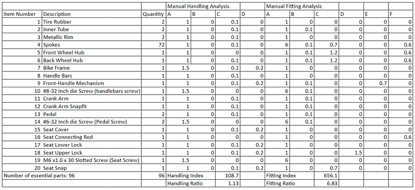
The ratio of the number of essential parts to the number of total parts is 60%, which is under the 100% threshold for the Lucas method.
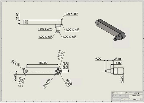
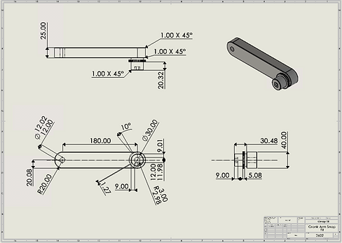
All parts on the aircraft were designed on the Solidworks CAD Software. I was responsible for designing the pedals, crankshaft, and crank arms.


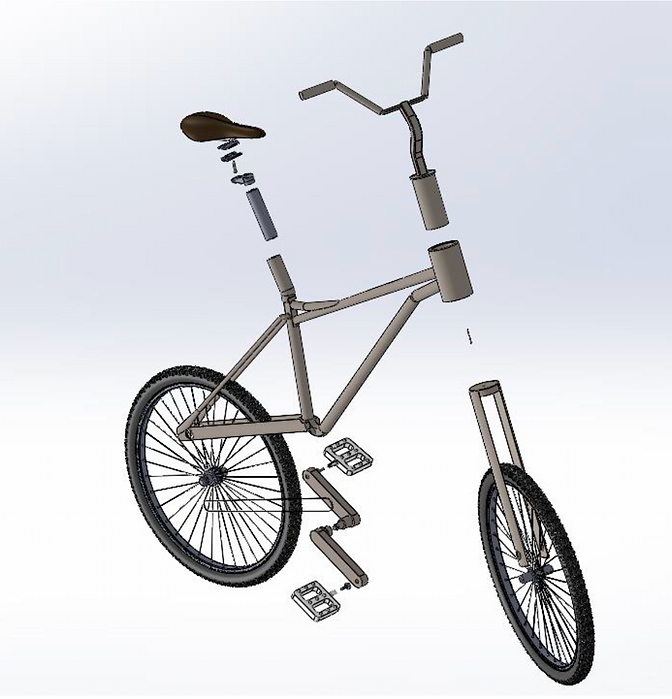
To match industry standards, bills of materials and exploded assemblies were also created.


Global Dimensioning & Tolerancing
Clearance and interference fits and standard tolerancing practice were used where necessary. As the pedal should be able to freely spin on the crank arm, a clearance fit was selected to connect these parts. Another clearance fit was used when securing the entire crank arm to the frame of the bike since the assembly needed to spin freely. These clearance fits also allowed for lubrication to be added between the given parts. As a snap fit locking mechanism was chosen for the crank arm and crank arm snap fit parts, an interference fit was selected.
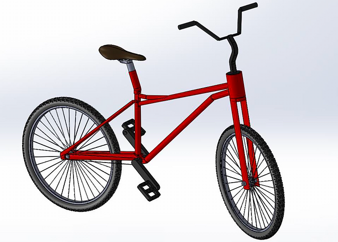
Result
After completing all parts, assemblies, and locking mechanisims on Solidworks, the following bicycle was designed.